My CNC router build
Here's a random collection of pics. I appreciate that there's almost no detail here.E-Mail me if you'd like to know more.
Having got the lathe to a decent level of functionality I decided that I needed to be able to tackle the third dimension.
I'd had an abortive attempt to convert a little milling machine previously. It ended badly. Many sleepless nights were spent agonising about the key issues:
- Buy a mill and retrofit vs construct
- Whether to build a moving table or gantry
- What type of ways to use
- etc..
As you can tell, I ended up deciding to build a machine from scratch. I hoped to minimise my risk by buying the Zoltar Design
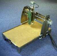
Chris sends a whole lot of drawings and instructional material. Certainly a bargain for what he asks. The machine, as specced, is a bargain basement unit that can be put together and driven with small motors for well under AU$1000.
This is really what I should have done :-(
Troy got the parts for a few machines laser cut in 304 stainless: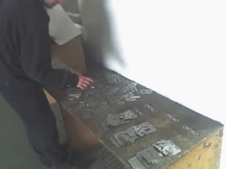 Troy did a great job nesting them and helping out in general. |
Full credit to Chris for an excelent "tab in slot" design. There are only about 4 bits to bond together with glue, everything else holds itself together with a minimum of tie rods and bolts.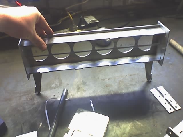 Of course I couldn't be happy with this. I lashed up a scratch TIG welder and did it the hard way.
It did come out a very rigid machine though |
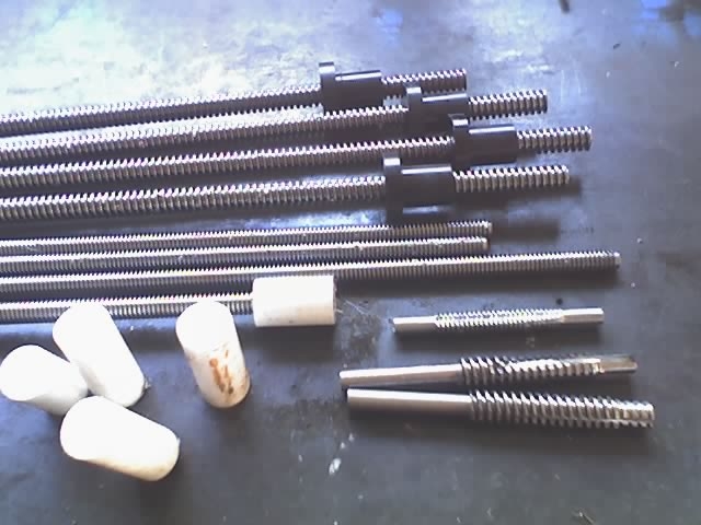 The original design used ACME leadscrews and plastic nuts, Craig managed to get hold of some nice ACME rod from the US for not a lot of money.
I made some taps. A bit of huffing and puffing later (an ACME tap removes a LOT of material) and we had some leadscrews. I used delrin for the nuts and they came out feeling nice. No backlash. |
|
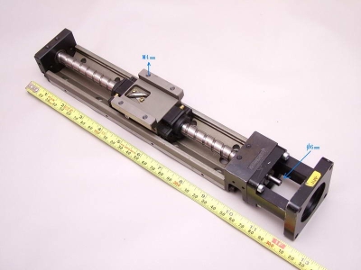
Then I won a ballscrew on EBay that I thought I'd cancelled my snipe on... A rummage through the junk box turned up a 10mm diam screw that was
the perfect length for the Z axis. And I start to think along the lines of "Well I'm only one screw away from a full set of ballscrews"... 10s of hours of fabrication later and I actually have a decent setup... It still looks a bit like Chris' design too. 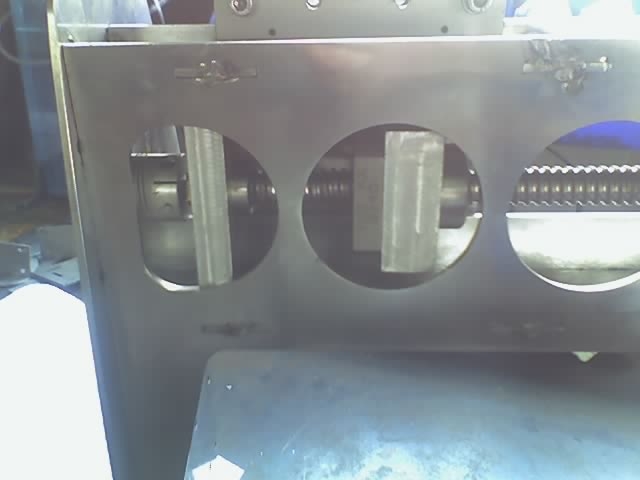 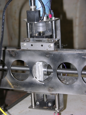 |
|
Having completed the Z and Y axis. And the driver boards too. I just had to test it, click the image to run some video. I was pretty happy with that. Those motors are spinning about as fast as they'll go, The plastic on metal bearings seem to be working well. Couldn't get the grin off my face! |
|
One of the cornerstones of the Zoltar design is use of polyethylene on stainless as a bearing material. Bangs for bucks it just cant be beat! It does
however requre that the rails that the blocks slide on be a fairly uniform width. Which mine were not. I can only guess that the sheet warped a bit
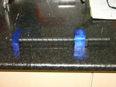
during laser cutting, because there was easily 1.5mm difference in width from one end of the rail to the other. The other Dave (many of my friends are called Dave, I find that it simplifies things) offered to help out and produced this monster workholding jig: 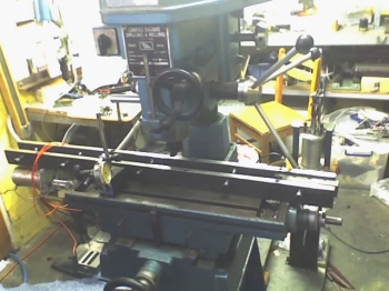 He clamped all the rails in that thing and spent about half a day at a local workshop on a big cylinder head grinder trying to get them even. At the end of this process they were about 1mm further out than they were when they started. It seams that the ginder was heating the stainless but only at one point. Stainless is a fairly poor conductor of heat so that point was getting VERY hot, expanding and getting ground down too much.. What a misery! The next bright idea was to fly cut them in Daves mill (that's the setup you see above. Catch is, the machine didn't have the travel to do the whole lengths and the job needed to be repositioned to finish the cut. Didn't come out too well :-(((. I went home after a long day licking my wounds.. Then I met another guy (who we'll call Dave to protect his real identity). Dave has this little shaper: Cick on the image to see some video of it doing a beautifull job on the rails. |
That job finally done, I was getting pretty close: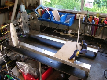 So I started to think about what to make the table out of. Again much sleep was lost. The design calle for MDF, but I really wanted to be able to use flood coolant on this machine. Aluminium was a bit pricy as was plastic and I was worried about differential expansion. I thought of fibrous cement sheet. You can get in 20mm slabs.. Then I dropped by a granite kitchen fabrication shop and they cut me a piece of synthetic granite from their scraps pile. It's really worth finding these places, as they have very little use for a bit of granite thats less than 600mm wide and will usually give it to you.. 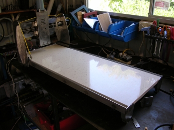 Did I make that? :-) |
|
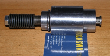
To attach the granite to things I made the worlds supply of Al threaded inserts on the CNC lathe using my recently constructed floating
tapping tool. These would be glued into holes drilled in the granite. 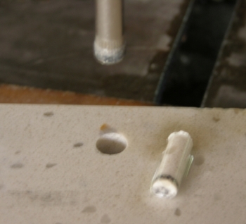 I purchased these 8mm diamond coring bits, which do a lovely job, if you have all day. They have a VERY nasty tendancy to jam and snap off the core, typically giving you about 0.5 seconds warning of this... I did about 10 holes in half a day. Obviously I wasn't going to drill the 100+ clamping holes with this. There was also the issue of holding the big slab of granite still while I worked on it.. And the fact the these drills and the tungsten tile drill I ended up using just wouldn't drill straight no matter what kind of jig I used, made the whole process of working with this stuff more hassle than it's worth. I'm very pleased with the result. But until I find a way of drilling accurate holes quickly, I can't recommend it to anyone. |
So now I had the thing pretty rigid, and I was able to get a feel for how it was going to move. I went to town on the X axis ballscrew mount
so that I'd have plenty of options when it came time to align everything: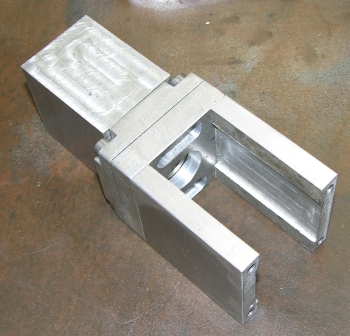 We set it up and started jogging X around, it was racking really badly. The bearing on one side would slip, then the one on the other, the end result being the gantry would waddle its way along the table... Back to the drawing board! Dave (does it matter which one?) lobbied for a loop of chain on each side with an axel linking the two. This setup works really well on his plasma table, but I was hoping for something a little simpler. Rod (Some people just refuse to conform!) has a router that is a fair bit bigger and uses skate bearings to great effect. I spent a great deal of time looking at it and decided that the main difference between his and mine wasn't the bearings, it was the bloody big plate he had bolted between the two sides of his moving gantry. I used his machine to make this: 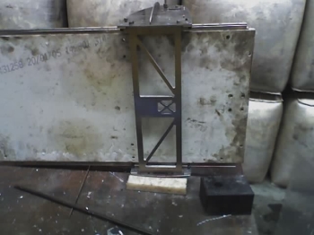 The more astute of you will notice that I also discarded the ployethylene on stainless rails and replaced them with IKO linear slides (oh feature creep, how I love you) Another 30 holes in that damn granite. A quick aside: A friend, let's call him Dave, came up with a really good way to minimise the hassle of mounting 2 linear rail trucks, all lined up with respect to one and other. 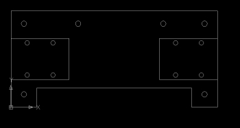 I machined 2 of these up on Rods NC router, the trucks locate into milled pockets and the whole plate is then mounted onto the moving bit, all alignment issues gone! While we're looking at the underbelly: I added a flexible arm to carry the cables: 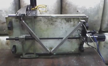 Things like this, and using good connectors, make the difference between a useful tool and a lash up and are well worth doing. |
|
I have some good pics and a video so I might as well talk about the feet. Having discarded the long rails I now needed something to lift the whole shebang off the table. The junk box yeilded some Delrin blocks and I was just starting to experiment with toolpath generators... Click on the image to see Rod's router cutting the feet out |
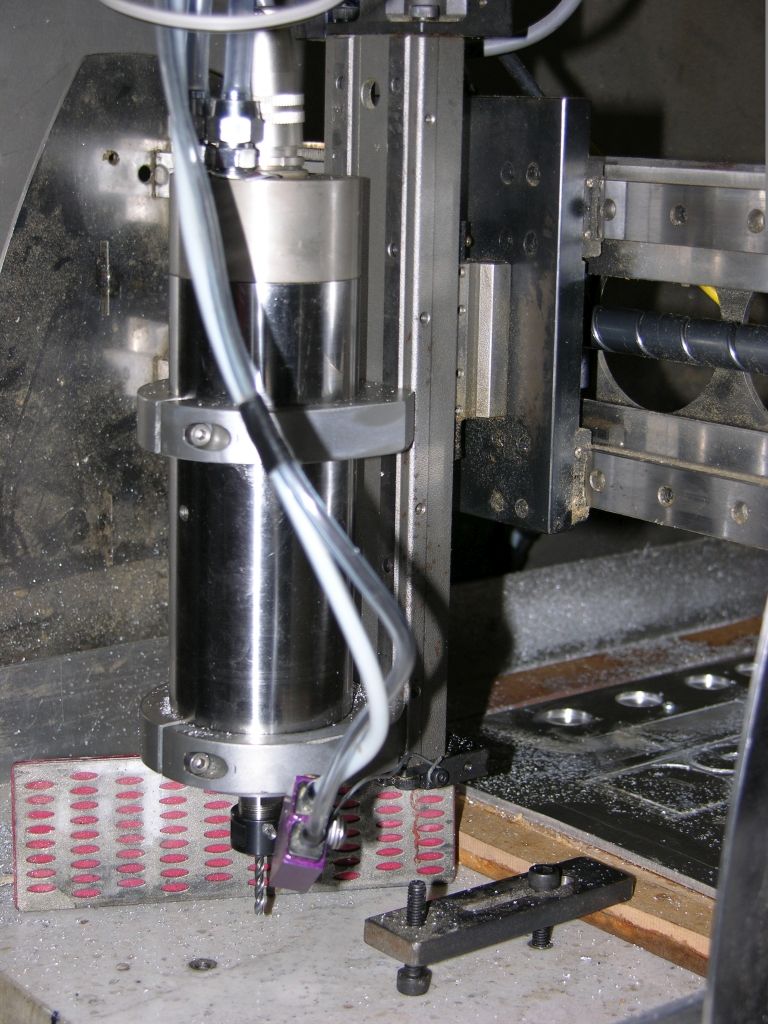
Spindles. Getting close now.. I knew that I wanted an automatic tool changing, all singing all dancing spindle. But when a 250W die grinder
came up on EBay I grabbed it as an interim solution: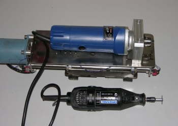 This thing has been great. I ended up adding a brace to the top, not because the grinder was flexing, but because the stainless back plate was flexing. One of the things that has really surprised me is that the little Jacobs chuck has NEVER let go of a cutter. |
|
Limit switchs... I use inductive proximity switches for all my limits (and the spindle index on my lathe and mill). These things are water, dust, noise, and bad day proof. To see how repeatable they are, click on the picture for some video. At about AU$10 each on EBay, you just cant do better than a prox. I did have one problem though. Initally I set up the Y axis proxes so that they tripped as the Y carriage moved towards them axially. 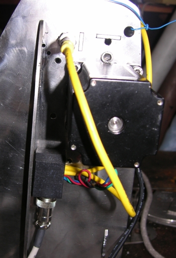 It worked well until I did some higher speed tests and realised that the drives couldn't decelerate the axis in the distance between the sensor range and the hard stop... So I made some brackets and mounted them perpendicular to the axis: 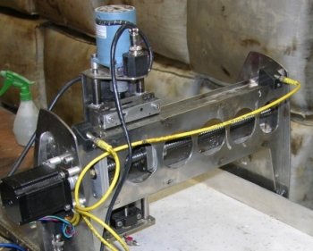 For the Z axis I have no limit switch on the upwards stroke. It's very rare that machine maxes out in that direction, and when it does, hitting the hard stop isn't such a big deal. If you change tools a lot though, you spend a lot of time zeroing Z against either the table or the job. This became quite an embuggerance so I made this: |
So she's mostly there now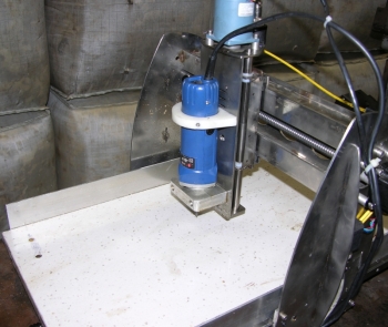 I've cut the obligatory Road Runner  (click to see a dry run) And had a well earned beer :-). |
How fast is it really
One of the things that really shits me about most CNC pages is that no-one fesses up about how fast their machines go.This machine will move 2.5m/min on all axis. If I had coarser pitch screws (and I do :-) it would go faster!
Whats Next?
Well I always wanted an autmatic tool changer. Anyone who's seen the Home Shop Accessories Inc product is sure to be bitten by that bug!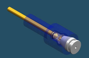
This is one of the designs I consiered.
I'm making progress, I've also made some tiny tool holders, these things are only 16mm in diameter and will take tooling up to 1/4"
I'm going to fit 20mm pitch ballscrews to increase the speed of the machine, I also have some THK linear rails for the Y axis.
There's lots more, including my working automatic tool changer on my spindles page
That'll be about it I reckon..
Who was I trying to kid!
The "PE on steel" linear bearings of the original design actually worked fairly well on the Y axis. But they still weren't up to the speed and rigidity I was chasing.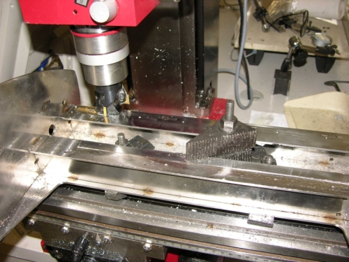
Here the face of the gantry is being machined flat in preparation for mounting a pair of linear bearings. If you're just starting out and trying to digest all the advice you've come across on the net then I strongly sugguest you write this, in big letters on something you look at regularly. "EVERYONE ENDS UP USING BALLSCREWS AND LINEAR BEARINGS". If some guy is bragging that his rolerskate bearing and water pipe contraption is just as good then he is either telling lies or has never used a machine with ball slides. There is simply nothing that will deliver the bangs for bucks value of a linear bearing.

You can see here the steel carrier plate I made up. I first made this out of 10mm alumninium, but it just wasn't rigid enough for that Z ais mount.
Ahhh, yes. The Z ais is gone too... Replaced with an all in one NSK linear stage. These things go for about AU$200 on ebay
They really are the perfect Z axis.
 You may also note that the pitch of the ballscrews has changed. I've finally got around to installing 10mm and 20mm pitch screws on this machine. Rather than go on about it, click on the image to the right for some video that demonstrates the improvements. Nb, The drives and motors are the same... |
The thing that amazes me is that I show this video to people and they still go out and fit 5TPI screws and buy 450OZ.in motors. Then wonder why their machines go so slow. If the pitch of your ballscrews is less than 10mm, then you should buy the highest current motors that will deliver the torque you need.
A 4A, 150OZ.in stepper will go about twice as fast as a 4A 450OZ.in stepper.
Automatic tool height setting
One of the embugerances of a small router is having to rezero Z each time you change a tool. Of course, skipping this step is an option I have (inadvertantly) taken a few times, the result being an immediate need to change the tool again.. :-(This little gadget makes life much easier. Click on the pic for a video...
In use, you change the tool, hit the "Auto Tool Zero" button in Mach3 and the Z offset is calculated automagically.
It's a bit of 1" diam hard chromed rod (ground flat by young George)in a steel sleeve with a switch in the bottom. I'm not really happy with the current switch (not enough over-travel) but it works a treat. You just sit it on the job or table under the tool and hit the
What's next?
The next chapter in this build is really all about spindles and has its own page hereAnd after that?
Wow did I ever get a lot of work out of that machine. It paid for itself at least 100 times over. Along the way it had a couple of upgrades and tweaks: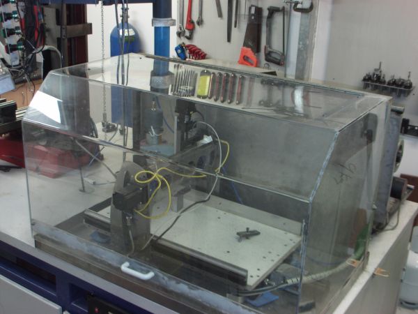
A polycarbonate enclosure
A 24000 RPM spindle (with mist coolant)
But eventually we grew out of it, so it went to a good home and we bought a slightly bigger machine....But that's a different story...