3 phase drive interface circuit for Mach 3
E-Mail me if you'd like to know more.Background
The only people who say there are better ways to drive a standard spindle than with a 3 phase motor and a variable frequency drive are those who don't own one!The proliferation of drives that take single phase in and produce three phase out means that these drives are appearing in more and more hobby workshops.
>
A typical VFD
If you're looking to buy, I'd recommend Automation Direct in Australia; they have 1Hp drives for about AU$250.
A 1Hp motor will set you back about AU$100, however I'd be surprised if you can't scrounge one for next to nothing.
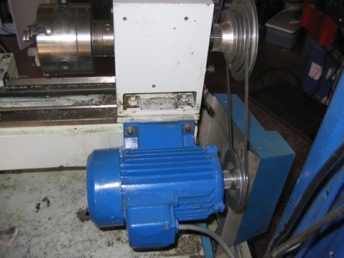
I picked up this 2Hp motor for AU$70, and it even came with a free pump that sold on Ebay for more than that! :-)
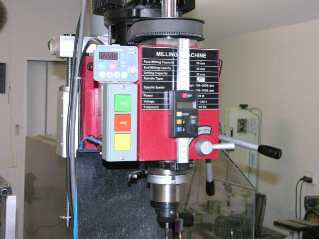
Click the image for a video of the X3 VFD doing it's thing
Here's the little 3/4Hp unit that was given to me for the lathe:
What's so cool about spindle speed control?
On a lathe you can change the speed for different diameters. Indeed, the G96 command will tell Mach 3 to vary the speed continuously with diameter... You just need to specify how many surface feet (or meters) per minute you want the tool to see...This is someone elses setup, but it demonstrates the principle.
Connections to the drive
Drives typically come with a speed control knob and a few start and stop buttons on their front panel. They also all come with some terminals to wire these controls in remotely. Their schematics typically look like this: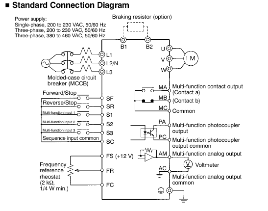
Forward/Stop and Reverse/Stop functions are pretty straight forward; you control them with relay outputs from your PC. The frequency reference is a bit trickier...
Fortunately, Mach3 has the ability to output a square wave signal with a duty cycle proportional to the requested motor speed. This technique is called Pulse Width Modulation or PWM.
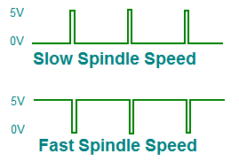
Mach3 output
Complicating things a little is that some drives have the common terminals of their connections at MAINS VOLTAGE!
Be very careful when wiring up any device at 110V or greater. ALWAYS unplug it and wait 60 seconds before touching the terminals!
My little circuit
The circuit below isolates the drive from the computer and converts the PWM output from Mach3 into an analog voltage for the drive. It also isolates the start and stop functions.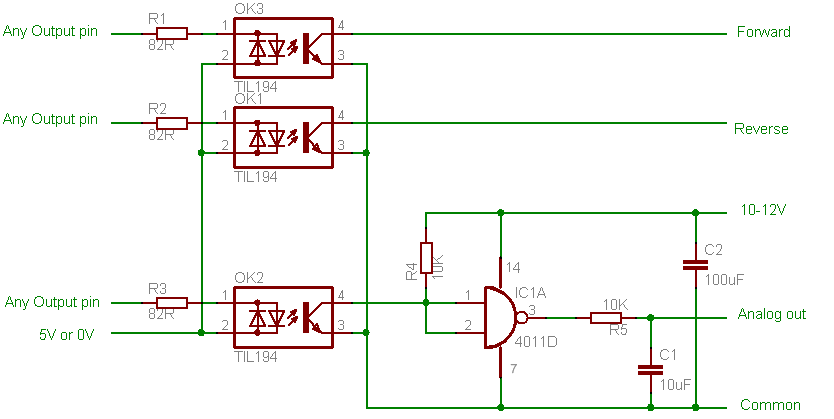
Setting it all up
I strongly recommend that you first get the drive and motor working with two switches and a potentiometer BEFORE installing this circuit. Most drives need to be told to take their commands from an external set of controls rather than their own front panel or network interface. Your drive may also need tuning to suit your motor, much better to do this before you make your setup more complex and getting it going this way can save you some confusion.At this point you need to figure out the top speed your setup will do. If you have a spindle speed sensor then this is easy. A handheld RPM meter is the next best thing. Failing that you'll need to work it out from frequency and pulley ratios.
When you're happy with it, hook up the Start and Stop functions to the interface board, leaving the potentiometer in place.
Go into "Mach 3"->"Engine Configuration"->"Ports and Pins" and configure two outputs using whatever parallel port pins you wired them to. Don't configure the PWM pin at this stage.
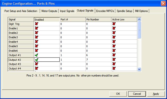
Go to the "Spindle Setup" tab; uncheck "Disable spindle relays" and enter the two outputs you configured in the previous step:
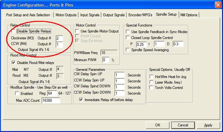
You should now be able to stop and start the motor using the M3 and M4 commands; speed will still be controlled using the potentiometer. If this doesn't work, check your wiring and try changing both output signals to Active Low
Next up, remove the potentiometer and wire up the analog out, common and 10V connections.
Go back to the ports and pin dialog in Mach and select the "Motor Outputs" tab:
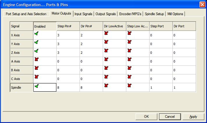
Configure both the step and direction outputs to the pin you wired the PWM signal to.
Go back to the "Spindle Setup" tab. "Use Spindle Motor Output" and check the PWM option:
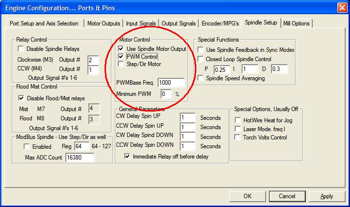
Set the PWMBase Freq to 1000Hz.
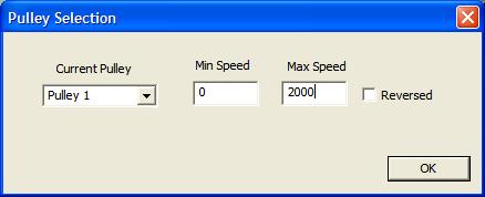
The final step is to tell Mach how fast the machine can go so it knows what speed to associate with each PWM duty cycle. You do this in the pulley config dialog ("Engine Configuration" -> "Spindle Pulleys"). Key in the top speed you worked out before:
At this point you should be able to start and stop the spindle and control its speed. If it goes faster when you tell it to go slower, then go back to the "Motor Outputs" tab of the "Ports and Pins" dialog and set the "Step and Dir" signals to active low.
There is a spindle speed mapping wizard that you can run which will have a good go at fine tuning the mapping between the PWM output and the speed. If you have a spindle speed sensor fitted then I recommend you run this. You can also use Machs PID (closed loop) functions. From my experience, this is unnecessary with a VFD.